
Drill and Blast Method
Drill and blast method is mostly used method for the excavation throughout the world. The method can be used in all types of rocks and the initial cost is lower than the mechanical method like TBM. This tunneling method involves the use of explosives. Compared with bored tunneling by Tunnel Boring Machine, blasting generally results in higher duration of vibration levels. The excavation rate is also less than TBM (usually 3 to 5m a day).
The typical cycle of excavation by blasting is performed in the following steps:
- Drilling blast holes and loading them with explosives.
- Detonating the blast, followed by ventilation to remove blast fumes.
- Removal of the blasted rock (mucking).
- Scaling crown and walls to remove loosened pieces of rock.
- Installing initial ground support.
- Advancing rail, ventilation, and utilities.

Advantages:
- Potential environmental impacts in terms of noise, dust and visual on sensitive receives are significantly reduced and are restricted to those located near the tunnel portal;
- Compared with the cut-and-cover approach, quantity of C&D materials generated would be much reduced;
- Compared with the cut-and-cover approach, disturbance to local traffic and associated environmental impacts would be much reduced;
- Blasting would significantly reduce the duration of vibration, though the vibration level would be higher compared with bored tunnelling;
Disadvantages:
- Potential hazard associated with establishment of a temporary magazine site for overnight storage of explosives shall be addressed through avoiding populated areas in the site selection process.
Drilling and Blasting Method Sequences
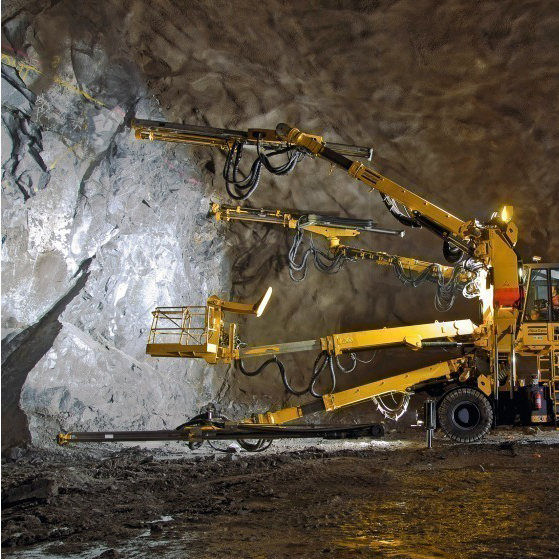
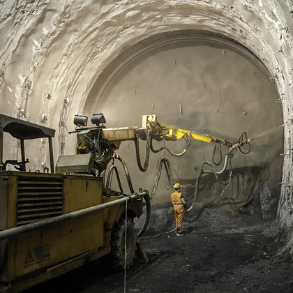
1- Drilling
Before the blasting takes place, the drilling rig bores the drill holes – determined in advance in a blasting plan – in the foremst front wall of the tunnel (working face). The more solid the rock, the more explosives are required.
A jumbo is used to drill holes in the rock face. This one has three drilling arms and an operator tower. It is run by electric cable; a hose brings water to the drills. The drills are pneumatic. That means that the drill bits both hammer and rotate. Broken bits of rock are flushed out by water. These drill holes are 2.4-3.6 metres long.
The first sets are straight holes (parallel cut) located around the edge of the face and in the middle. A second set (V-cut) is angled toward the center. These allow the rock to be blown away from the face into the drift (tunnel).
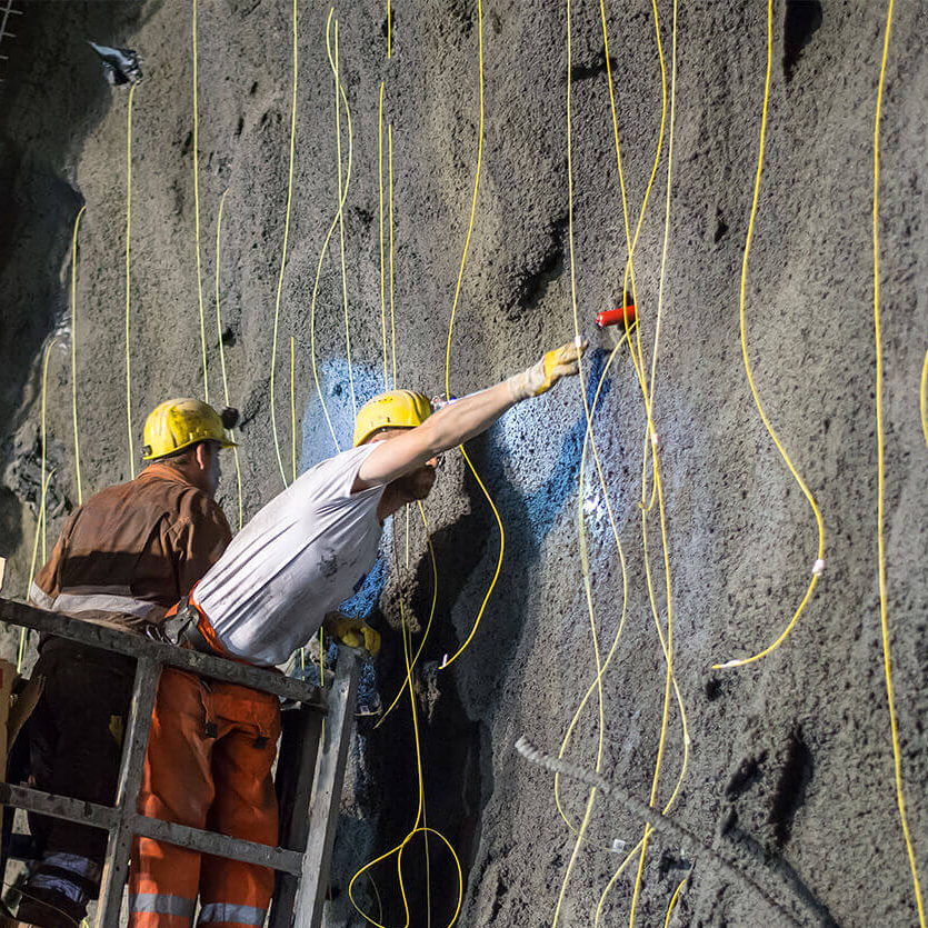
2- Loading and Blasting
The drill holes are now filled with explosives, detonators are attached to the explosive devices and the individual explosive devices are connected to one another. The holes are blasted in a proper sequence, from the center outward, one after the other. Although more than 100 explosions may be set off, one after the other, the blastsequence is completed in several seconds. The devices should not explode at the same time, but rather one after the other at specified intervals. Only when the blast master has ensured that nobody is left in the danger zone can the explosion be triggered by the blasting machine.
3- Ventilating
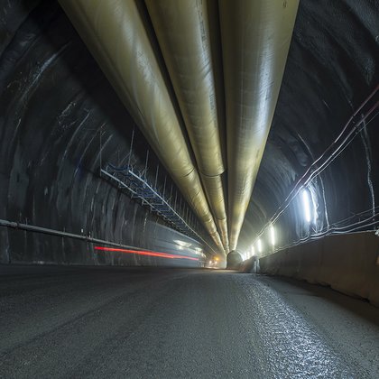
The blast causes lots of rock to be flung through the tunnel, dispersing clouds of dust that then mix with the combustion gases of the explosion. So that the miners can resume work in the tunnel, the bad air must be removed from the tunnel. This is done by using so-called air-ducting systems, long steel or plastic pipes, which are attached to the roof of the tunnel and blow fresh air onto the working face. This gives rise to localized excess pressure and the bad air is pushed towards the tunnel exit.
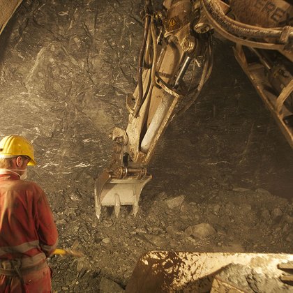
4. Dislodging
Dislodging refers to the stripping away and removal of loose pieces of rock, which were not completely released from the rock during the blasting procedure. This working step is completed by a robust tunnel excavator.
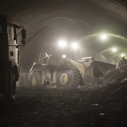
5. Removing rubble
After the loose pieces of rock have been dislodged from the working face, the blasted material – the rubble or spoil – is carried out of the tunnel. The material is either loaded onto dump trucks with wheel loaders and taken from the tunnel to an outside landfill or it is transported from the site of excavation to the landfill on conveyer belts. During the construction of the Brenner Base Tunnel, the transportation of the excavated material mainly takes place automatically using conveyor belts.
6. Securing
The quickly drying shotcrete used for this purpose in particular enables a cavity-free connection of the securing mechanism to the rock. Depending on the type of rock, a variety of securing measures can be implemented: wire mesh, tunnel arches, stakes or so-called bolts, which can be driven into the rock.
The final method for stabilizing rock faces is most commonly rock bolting. A jumbo is used here to first drill holes into the rock. The holes vary from 2.4-6 metres long. Next a steel rod with a wedge threaded on the end is inserted in the hole. When it is in place, the rod is turned so that it pulls out against the wedge, forcing it into the walls of the hole. The outside end of the rod is secured with a steel plate and large nut. Geologists and engineers at a mine determine the spacing and depth of rock bolts required for the conditions at their site.
Under the poorest ground conditions it may be necessary to put steel arches in place to hold up the walls and roof of a tunnel. In other situations a steel mesh may be secured to the walls and roof to prevent other loose materials from falling on workers below.
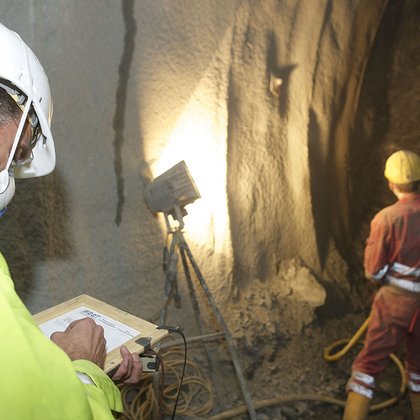
7. Geological mapping
The working face is now freely accessible and the geologist has a few minutes to map it. In the process, he determines what type of rock is present and how the rocks lie, i.e. whether they dip in a flat or steep manner, whether they are folded or even broken. He uses a special compass as an aid to measure the angle of incidence and direction of incidence of the rock structures. At the same time, the strength of the rock, the reaction of the rock mass to the excavation process and any mountain water infiltration are also documented. The mapping report created from this – with sketches and photos – serves as the basis for the selection of appropriate supporting measures.
Drilling Patern Design
The drilling pattern ensures the distribution of the explosive in the rock and desired blasting result. Several factors must be taken into account when designing the drilling pattern: rock drillability and blastability, the type of explosives, blast vibration restrictions and accuracy
requirements of the blasted wall etc. The basic drilling & blasting factors, and drilling pattern design are discussed below. Since every mining and construction site has its own characteristics, the given drilling patterns should be considered merely as guidelines.
Many mines and excavation sites still plan their drilling patterns manually, but advanced computer programs are available and widely used. Computer programs make it easier to modify the patterns and fairly accurately predict the effects of changes in drilling, charging, loading and production. Computer programs are based on the same design information used in preparing patterns manually.
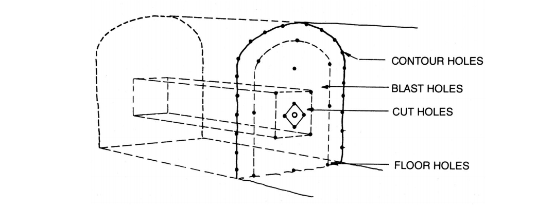
Drilling pattern design in tunneling and drifting is based on the following factors:
- Tunnel dimensions
- Tunnel geometry
- Hole size
- Final quality requirements
- Geological and rock mechanical conditions
- Explosives availability and means of detonation
- Expected water leaks
- Vibration restrictions
- Drilling equipment
Depending on site conditions, all or some of the above factors are considered important enough to determine the tunnel drilling pattern.Construction sites typically have several variations of drilling patterns to take into account the changing conditions in each tunnel. Drifting in mines is carried out with 5 to 10 drilling patterns for different tunnel sizes (production drifters, haulage drifters, drawpoints, ramps etc.) The pattern is finalized at the drilling site.Tunnel blasting differs from bench blasting in that tunnels have only one free surface available when blasting starts. This restricts round length, and the volume of rock that can be blasted at one time. Similarly, it means that specific drilling and charging increases as the tunnel face area decreases.When designing a drilling pattern in tunneling, the main goal is to ensure the optimum number of correctly placed and accurately drilled holes. This helps to ensure successful charging and blasting, as well as produce accurate and smooth tunnel walls, roof and floor. A drilling pattern optimized in this way is also the most economical and efficient for the given conditions.
Sources: bbt-se.com; mineralsed.ca; Rock Excavation Handbook (Sandvik Tamrock Corp.)
Videos;